Landfill Kapiteltal Kaiserslautern - Construction of a new landfill section / DKI expansion
Integration of GREEN TERRAMESH system solution in the realisation of the development measure of the new landfill section. Construction of a new landfill access road
Introduction
Zentrale Abfallwirtschaft Kaiserslautern - gemeinsame kommunale Anstalt der Stadt und des Landkreises Kaiserslautern (ZAK) has been operating the Kapiteltal landfill northeast of the city of Kaiserslautern since the mid-1970s.
The landfilling of untreated waste (mainly household and commercial waste from the city and district of Kaiserslautern) was completed in 2000, and landfill operations were terminated in mid-2005. Since then, the landfill has been in the decommissioning phase.
Based on the planning approval decision of October 2013, ZAK intends to expand the Kapiteltal landfill by adding a DKI landfill section above the old landfill body (landfill on landfill). According to the approval planning on which the planning approval decision is based, the DKI landfill section is to be constructed in six construction phases (BA). The first construction phase (DKI BA 1 A and B) is to be available for landfill operations on 1 January 2016.
The utilisation of the new landfill section requires a modified development concept.
In essence, a new northern access road to the landfill is to be constructed for this purpose. An essential part of this new access road is the construction element ‘reinforced earth’ GREEN TERRAMESH as a steep slope system.
Location description
Topography
The Kapiteltal landfill is part of the Kaiserslautern waste management centre and can be reached via the L 401 road. The Kapiteltal is a former dry valley and is flanked by the slopes of the Sulzberg in the north and the Kleiner Meisenberg in the south-east and slopes from north-east to south-west towards the Eselsbach.
The original traffic route, which is to be largely decommissioned in the future, runs from the gate facility located in the north-east (approx. 331 m above sea level) (see Figure 1, route marked in yellow) to the operating points located in the south-west, first to the low point area of the old landfill (approx. 280 m above sea level), then further uphill to the entrance to the storage area (approx. 310 m above sea level) and from there descends to the original low point area of the dry valley (approx. 245 m above sea level).
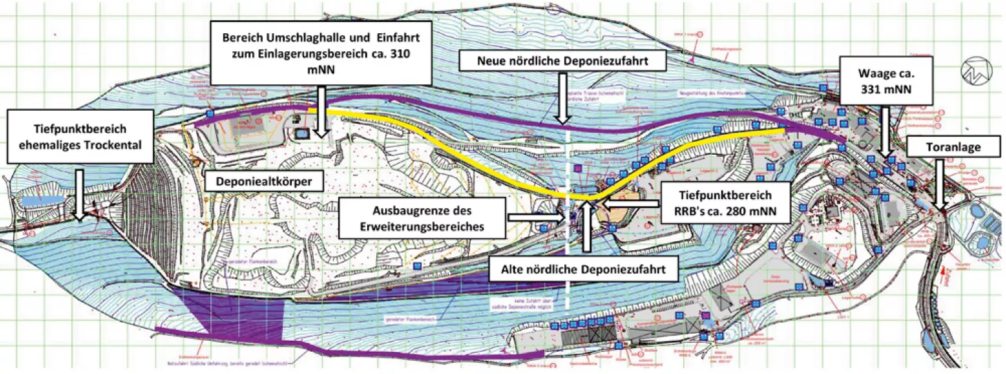
Figure 1: Site overview showing the access situation to the landfill body
Geological conditions
The Kapiteltal landfill is located in the lower red sandstone distribution area. The entire landfill bottom is located directly in the loosening area of the rock zone of the Upper Trifels layers (red sandstone sediments), which are partly overlaid by slope and weathering debris in the flank area. Only in the area of the valley axis of the Kapiteltal are the sandstone sequences of the Trifels layers covered by thicker deposits of weathered sands.
The new road route runs in large areas in the natural soil.
In the area around the gate facility / weighbridge, which is home to a large number of operational facilities (biomass power plant, recycling centre, hazardous waste collection, etc.), the topographical conditions mean that level operational areas can essentially only be created by backfilling. Against this background, the subsoil in the critical connection area of the route of the new northern access road is characterised by artificial fillings. These are predominantly a mixture of gravel and sand with a low proportion of fines. In some areas, thin topsoil and light brown fine sands have replaced the fillings. They form the original slope cover. Investigations carried out have shown that the rock horizon runs at 1.9 - 7.0 m below ground level.
Construction project
Planning phase
The new landfill section ‘landfill on landfill’ had to be designed in such a way that the old northern access road had to be largely decommissioned and dismantled. The search for a new route (see Figure 1, route marked in purple) was severely restricted by the steep and partially cramped site conditions, and ultimately focussed on the expansion of an existing forest path / farm track on the north-eastern flank of the Sulzberg.
The planning challenge in this case was to connect the new route area to the existing transport route network. A variety of technical solutions had to be developed in order to take into account the infrastructural conditions, the steep slopes, the confined space and the large number of technical and infrastructural facilities in the connection area.
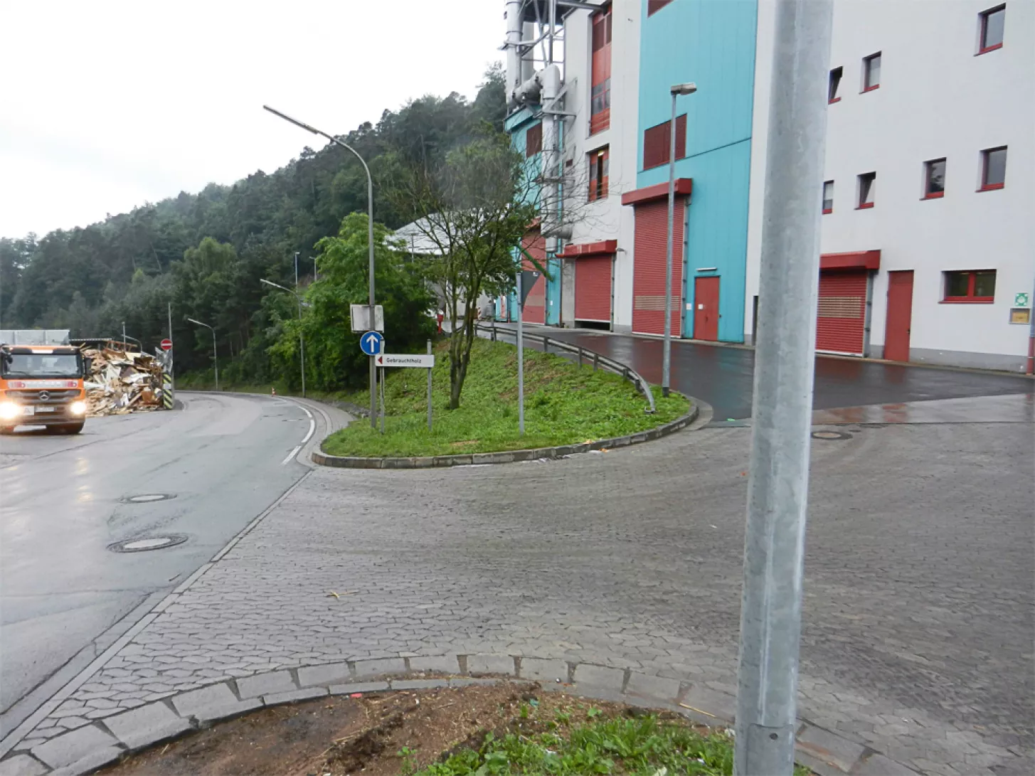
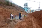
Figure 2: Initial situation with used wood processing area (storage location 3), exit to the low point area of the landfill (RRBs), access to the biomass power plant and drive past it to the area of the forest path / service road of the main route (from left to right).
Due to the steep gradient of the existing landfill access road, which must continue to ensure accessibility to various operating areas, a large difference in height must be overcome - over a comparatively short distance - when connecting the new route to the old access road.
The original planning initially envisaged a combination of a retaining wall made of angle sections (for smaller height differences to be overcome) and a back-anchored bored pile wall. In the course of increasing planning detailing, it was decided to dispense with the realisation of a bored pile wall. The reasons for this were, on the one hand, the difficulty of integrating back anchoring (due to the existing building and infrastructure). On the other hand, however, economic aspects essentially led to the exclusion of this variant.
From this point on, the problem solution focussed exclusively on the use of ‘reinforced earth systems’ for larger height differences to be overcome (see Figure 3.), whereby the use of angle profiles was indicated for smaller height differences.
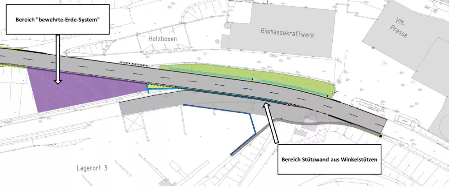
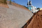
Figure 3: General overview of the connection node with a combined slope support consisting of angle supports and ‘reinforced earth systems’
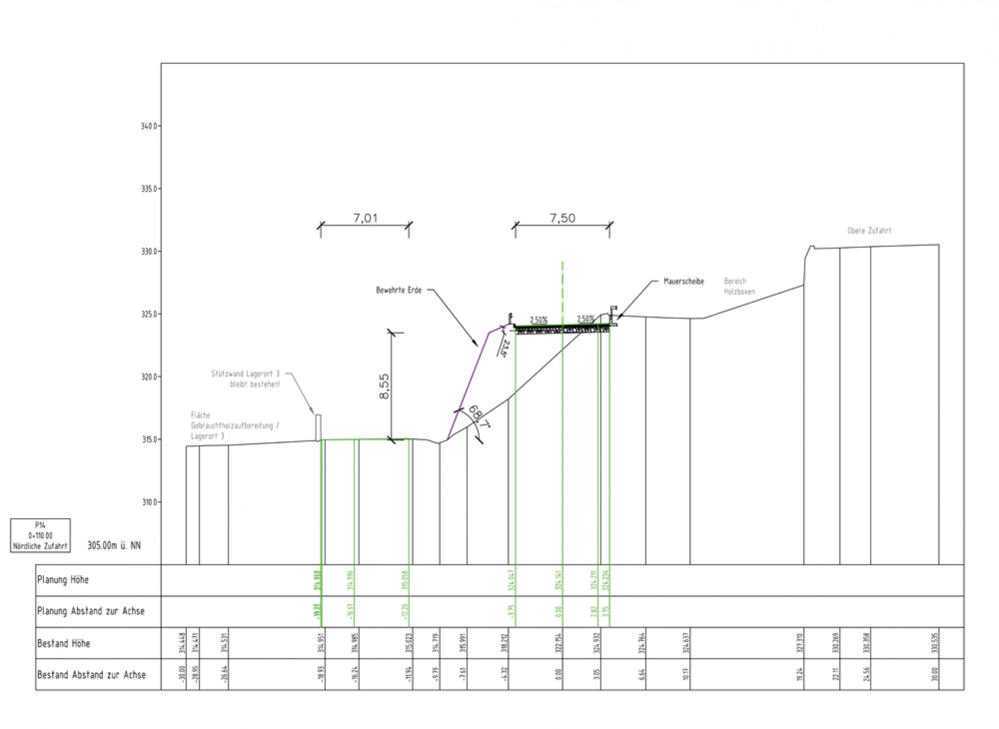
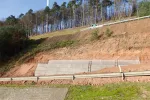
Figure 4: Use of angled supports in areas with low height differences to be overcome
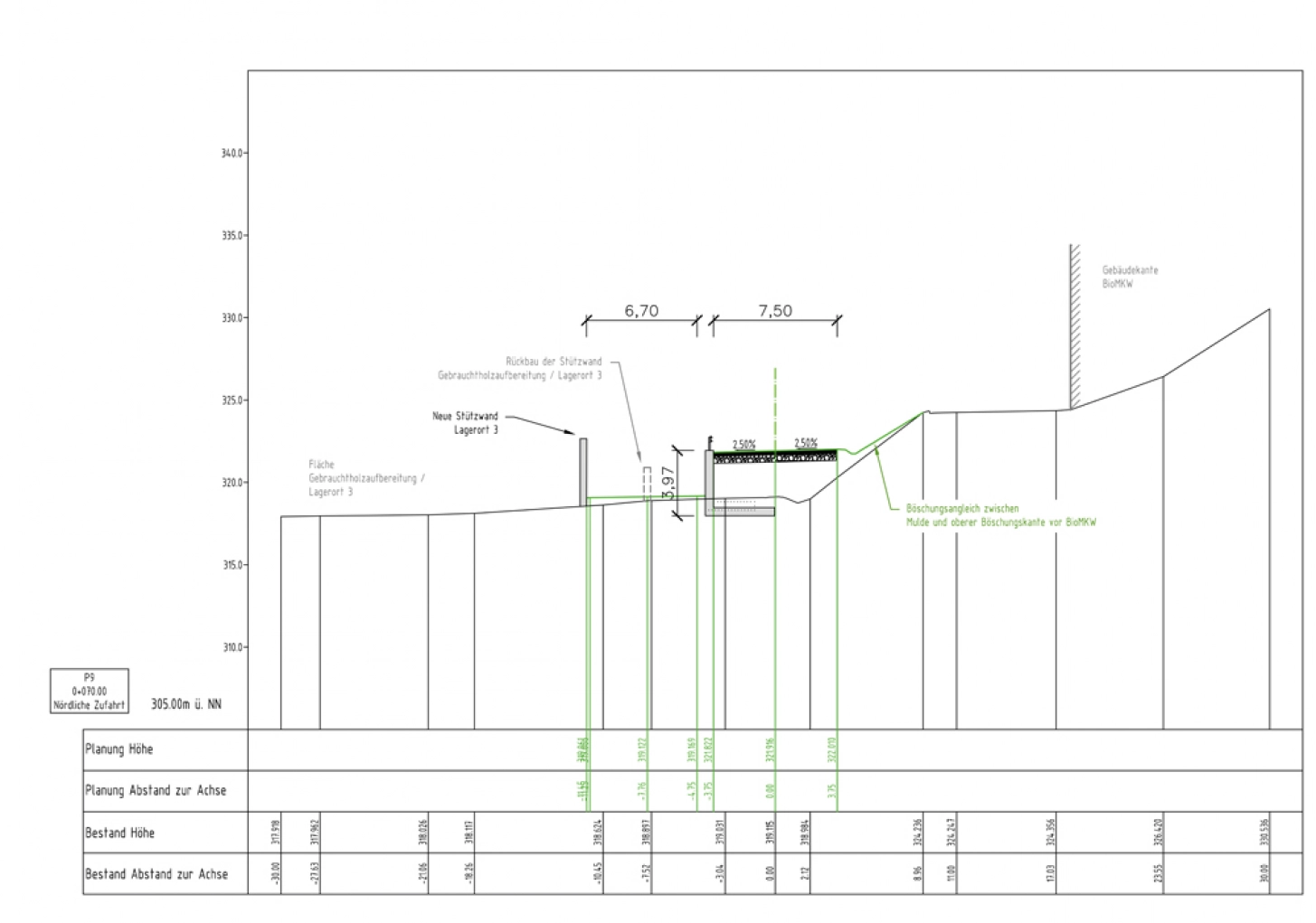
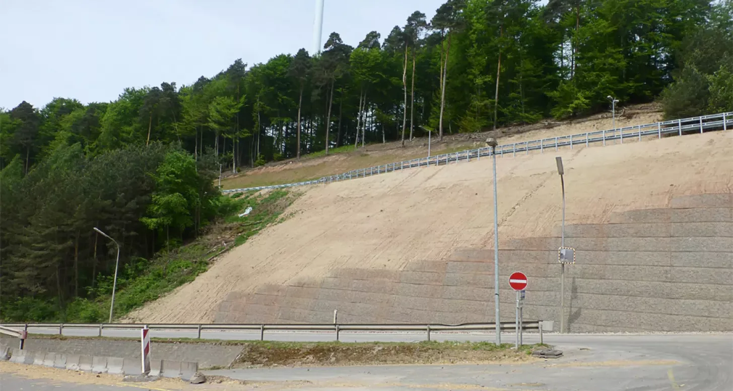
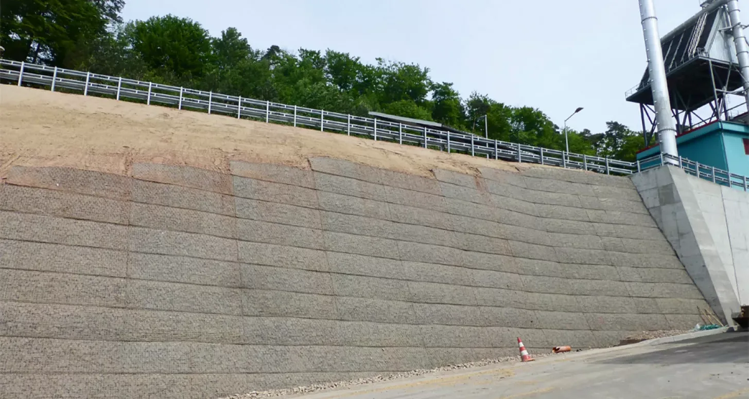
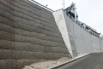
Figure 5: ‘Reinforced earth systems’ in areas with high height differences to be overcome.
Realisation phase
During the realisation phase, the project was further specified and optimised. The GREEN TERRAMESH steep slope system was selected as the system to be used for slope stabilisation (length approx. 55 m, maximum height difference approx. 9.5 m). This system was best suited to the general (cost and time) as well as project and site-specific conditions and framework conditions (topographical conditions, infrastructure and development, flexibility and work safety).
Time
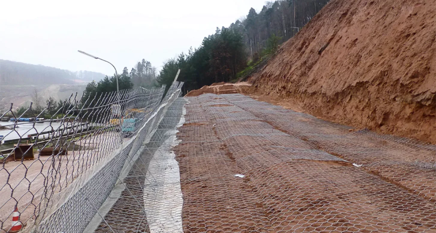
The GREEN TERRAMESH system offers time advantages during realisation. The individual elements are prefabricated, prepared on site and then transported to the construction area and installed using compacted backfill.
Costs
The overall system also offered monetary advantages in the application. The material costs were somewhat higher compared to conventional reinforcement elements. However, together with the associated earthworks and the time advantages already mentioned, economic savings were achieved in this case.
Installation
After brief instruction from the manufacturer, the GREEN TERRAMESH system was easily erected, installed and backfilled by the contractor. In this case, the visible surfaces were not subsequently greened and instead a coarse-grain backfill was used as an optical element during installation. The realisation of this visual element was also carried out without any problems. The system also offers direct trafficability and therefore the greatest possible installation flexibility.
Occupational safety
Setting up and anchoring the front element during installation prevents materials from the backfill or backfill from leaving the installation level (prevention of rockfall towards the foot of the embankment). In this case, particular importance was attached to this advantage, as constant vehicle traffic was to be expected along the foot of the embankment, even during the construction work.


